


U0012
Share with Mechanic
Network & CAN-Bus Communication
Standard OBD-II Diagnostic Protocol
Fault Description & Technical Meaning:
Medium Speed CAN Communication Bus (+) Open. This diagnostic trouble code indicates a broken wire, disconnected coupler, or internal open circuit causing complete loss of electrical connection. The Controller Area Network (CAN-Bus) Communication Lines transmits high-speed digital serial data packets between vehicle computers (ECU, ABS, Instrument Cluster, and BCM). When this circuit fails, the vehicle computer illuminates the Check Engine / Warning Light and may log an active diagnostic fault code.
Diagnostic Summary: Diagnostic code U0012 triggers due to a circuit open affecting the Controller Area Network (CAN-Bus) Communication Lines, impacting proper vehicle operation.
Related Components (Photo & Inspection)
3 Components (Tap to Zoom)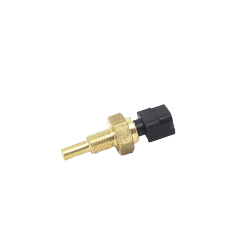
Sensor
EOT Sensor (Engine Oil Temperature)
Click to inspect photo & test specs
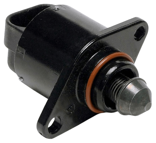
Actuator
Idle Air Control Valve (ISC/IACV)
Click to inspect photo & test specs
Electrical
12V Motorcycle Battery
Click to inspect photo & test specs
Common Symptoms
- • Check Engine Light (MIL Lamp): Illuminates or flashes on the speedometer console.
- • Engine Hesitation & Jerking: Poor throttle response during sudden acceleration.
- • Drop in Fuel Economy: Open-loop fuel spraying increases petrol consumption and causes black smoke.
- • Hard Cold Starting: Engine dies during idle or requires multiple starter button attempts.
Common Root Causes
- • Wiring Harness Damage: Chafed wires touching motorcycle frame metal or rodent cuts.
- • Loose / Corroded Coupler: Green oxidation or loose push-fit pins inside connector plug.
- • Defective Component: Burnt internal sensing thermistor or solenoid actuator coil.
- • Low Battery Voltage: Weak motorcycle battery under 12.0V causing ECU reference error.
Step-by-Step Diagnostic & Repair Procedure
Bench-tested repair procedure for code U0012
Step 1:
Turn off the vehicle ignition switch, remove the key, and allow all electrical and mechanical systems to cool down completely. Locate the Controller Area Network (CAN-Bus) Communication Lines, typically positioned routed through the main vehicle wiring harness backbone and accessible at the diagnostic OBD-II port.
Step 2:
Carefully unplug the electrical wiring coupler from the Controller Area Network (CAN-Bus) Communication Lines. Inspect the connector pins and socket terminals for green copper corrosion, water moisture, bent pins, or melted plastic. Trace the wiring harness back toward the control module and check for chafing, wire cuts, or melted insulation touching vehicle metal.
Step 3:
Set a digital multimeter to DC Volts and turn the ignition key ON without starting the engine. Check for proper electrical reference voltage (5.0V reference or 12V battery power depending on component specification). Next, set the meter to Ohms (continuity) and test for continuity (0 Ohms) along the harness wires and check for infinite resistance (open circuit) indicating a severed wire to ensure the ground circuit has less than 0.5 Ohms resistance to the chassis ground.
Step 4:
Bench-test the component by measuring its internal resistance across the electrical terminals using your multimeter (resistance across CAN-H and CAN-L pins (must measure approx 60 Ohms with battery disconnected) and CAN-H voltage (~2.5V-3.5V) / CAN-L voltage (~1.5V-2.5V) with key ON). If the component is carbon-fouled, contaminated, or has poor pin tension, clean it carefully using dedicated electrical contact cleaner. If the internal coil or sensor circuit shows zero Ohms (short) or infinite Ohms (open), replace the component with a genuine OEM part.
Step 5:
Reconnect the electrical coupler firmly until the locking tab audibly clicks into place. Connect an OBD-II diagnostic scanner or use the OkBike Mechanic App to erase stored DTC fault memory from the ECU. Start the engine or power up the vehicle, perform a test drive covering varied speeds, and verify that the Warning Light remains permanently turned off.
Important Note: Simply replacing the sensor does not immediately clear the Check Engine Light (MIL). Connect an OBD-II scanner to the motorcycle diagnostic connector and execute "Erase Stored DTC Memory" followed by a road test.
Related Diagnostic Fault Codes
U0009
High Speed CAN Communication Bus (-) shorted to Bus (+). This diagnostic trouble code has detected an abnormal operating condition or electrical signal failure. The Controller Area Network (CAN-Bus) Communication Lines transmits high-speed digital serial data packets between vehicle computers (ECU, ABS, Instrument Cluster, and BCM). When this circuit fails, the vehicle computer illuminates the Check Engine / Warning Light and may log an active diagnostic fault code.
U0010
Medium Speed CAN Communication Bus. This diagnostic trouble code has detected an abnormal operating condition or electrical signal failure. The Controller Area Network (CAN-Bus) Communication Lines transmits high-speed digital serial data packets between vehicle computers (ECU, ABS, Instrument Cluster, and BCM). When this circuit fails, the vehicle computer illuminates the Check Engine / Warning Light and may log an active diagnostic fault code.
U0011
Medium Speed CAN Communication Bus Performance. This diagnostic trouble code indicates an in-range rationality fault where the sensor is sending a signal, but the value contradicts other sensor readings or expected physical limits. The Controller Area Network (CAN-Bus) Communication Lines transmits high-speed digital serial data packets between vehicle computers (ECU, ABS, Instrument Cluster, and BCM). When this circuit fails, the vehicle computer illuminates the Check Engine / Warning Light and may log an active diagnostic fault code.
U0013
Medium Speed CAN Communication Bus (+) Low. This diagnostic trouble code indicates that signal voltage has dropped below the minimum calibrated threshold (typically indicating a short-circuit to chassis ground or a dead sensor). The Controller Area Network (CAN-Bus) Communication Lines transmits high-speed digital serial data packets between vehicle computers (ECU, ABS, Instrument Cluster, and BCM). When this circuit fails, the vehicle computer illuminates the Check Engine / Warning Light and may log an active diagnostic fault code.
U0014
Medium Speed CAN Communication Bus (+) High. This diagnostic trouble code indicates that circuit voltage exceeds the maximum allowable threshold (typically indicating a short-circuit to 12V battery power or a missing ground). The Controller Area Network (CAN-Bus) Communication Lines transmits high-speed digital serial data packets between vehicle computers (ECU, ABS, Instrument Cluster, and BCM). When this circuit fails, the vehicle computer illuminates the Check Engine / Warning Light and may log an active diagnostic fault code.
U0015
Medium Speed CAN Communication Bus (-) Open. This diagnostic trouble code indicates a broken wire, disconnected coupler, or internal open circuit causing complete loss of electrical connection. The Controller Area Network (CAN-Bus) Communication Lines transmits high-speed digital serial data packets between vehicle computers (ECU, ABS, Instrument Cluster, and BCM). When this circuit fails, the vehicle computer illuminates the Check Engine / Warning Light and may log an active diagnostic fault code.
